Thursday 13 December 2012

Digital Image Processing

WHY USE DIGITAL IMAGE PROCESSING?
  • It provides a flexible environment in which to experiment
  • You can MANIPULATE
            TRANSFORM
            ENHANCE      your images and photographs
CCD
Charge Coupled Device
This is either a linear or matrix array of photosensitive electronic elements that captures the image through either a lens or a detector.


  • Digital cameras capture images through and area array sensor. This is a grid that uses hundreds of thousands of microscopic photocells to create picture elements (pixels) by sensing the light intensity in small portions of the image formed through a lens system.
PIXELIZATION
Pixelization can occur when the sensor array resolution is too low. You can remedy this by increasing the number of cells in the sensor array as this increases the resolution of the captured image. 


DIGITAL CAMERA COLOUR
Digital cameras capture colour images by placing upto 3 filters over the photocells, these colours are:

  1. Red
  2. Green
  3. Blue
Each photocell is assigned three 8bit numbers (up to 256 levels), these correspond to the red, green and blue brightness value.

RED- 227
GREEN- 166
BLUE- 97

DIGITAL CAMERA OPTICS
Before a digital camera focuses the light collected on to the sensor array it has to pass it through and optical low-pass filter, this:
  • Excludes picture data beyond the sensor's resolution
  • Compensates for false colouration caused by drastic changes of colour contrast
  • Reduces infrared and non-visible light
A PIXEL IS THE SMALLEST DIGITAL IMAGE ELEMENT
MANIPULATED BY IMAGE PROCESSING SOFTWARE.


DYNAMIC RANGE: This is the number of colours or shades of grey used in a visual scene. In a digitised image the dynamic range is fixed by the number of bits that the digital system uses to represent each pixel in an image. 


WHAT IS DIGITAL IMAGE PROCESSING?
  • Analysis:
    Operations provide information on photometric features of an image eg. colour count, histogram.
  • Manipulation:Operations change the content of an image eg. flood fill, crop. Input image yields output image.
  • Enhancement:Operations attempt to improve the quality of an image in some sense eg. heighten contrast, edge enhancement. Input image yields output image.
  • Transformation:
    Operations alter the image geometry eg. rotate, skew. Input image yields output image.


Wednesday 12 December 2012

The Little Ducks

For this lab we had to edit together raw camera videos of ducks near a pond and add music to create a minute long piece of work. We got a choice of videos and different music we could add to the piece. I chose to keep mine classical and edited the footage so that scenes faded into each other so that it looked smooth. I also chose to edit the video into a sepia tone as I thought it looked good and fitted in with the theme I had decided to do.

http://www.youtube.com/watch?v=MZUUVyzmS30&feature=youtu.be

Here is the link to the video which I have uploaded to YouTube.


The Human Ear


The human ear's auditory system can detect rapid changes in sound intensity (dB) and frequency (Hz). We hear this as loudness and pitch.
The auditory system converts changes in air pressure to neural activity, sending signals that allow the brain to attach meaning to the sounds that we hear.

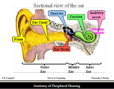
There are different parts to the ear; the outer ear, the middle ear and the inner ear. Each are responsible for different, specific functions in hearing. 

OUTER EAR
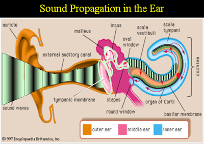
Soundwaves are first collected here, in the outer ear, by the Pinna(outer ear) which is shaped in order to amplify sound and figure out sound location. This leads into the ear canal which leads to the eardrum.

MIDDLE EAR
The soundwaves vibrate your eardrum, this in turn causes the Malleus, Incus and Stapes (3small bones) to vibrate. The Stapes then vibrates a small membrane at the base of the Cochlea.


INNER EAR
It is here in the inner ear where the complex structures convert sound into neural activity so that your brain can process it. 


If you were to 'unroll' the Cochlear and look inside you would see the Basilar membrane. The Basilar membrane vibrates in response to the sound transmitted to the fluid-filled Cochlea by deflections in the middle ear. 


High Frequency sounds displace the stiff base.
Mid Frequency sounds displace the middle of the Basilar membrane.
Low Frequency sounds displace the Apex.


Digital Signal Processing


A Digital Signal Processor (DSP) needs:
  • Input and Output filtering
  • Analogue to Digital to Analogue conversion
  • A digital processing unit
DSP's are used for PRECISION, ROBUSTNESS and FLEXIBILITY. 

Precision: In theory it is just the precision of DSP systems that is limited by the conversion process at input and output. However in reality it is the sampling rates and word length restrictions that modify this. The increasing operating speed and word length of modern digital logic is allowing many more areas of application.

Robustness: Digital systems are less susceptible to electrical noise pick up and component tolerance variations than analogue systems. Adjustments for electrical drift and component aging are essentially removed which is important complex systems.

Flexibility: It's programmability allows you to upgrade and expand the process operations without incurring large scale hardware changes. You can construct practical systems with time varying and adaptive characteristics. 


In the above diagram the sampling frequency defines the number of samples per unit of time taken from a continuous signal to make a discrete signal.

The inverse of the sampling frequency is the sampling interval, which is the time between samples.

QUANTISATION
The majority of modern soundcards support 16bit word length coding, of the quantised sample values.
This represents 65536 different signal levels within the input voltage range on the soundcard.

EG. If the voltage range of an input connection is +/-5V, the range is 10V. A 16bit system therefore has a quatisation step of (10/65536V) = 0.15mV. 
And this is the smallest voltage difference from this system.

DYNAMIC RANGEThe dynamic range is the ratio of the largest signal amplitude to the smallest.To calculate the dynamic range:
20log([Voltage Range]/{Quantisation step size})dB
=20log(65536)dB
=96dB

In the human ear, we have a dynamic range of >120dB


Wednesday 5 December 2012

Generating Signals with GoldWave


Here is a screenshot of a 400Hz sine wave with 8 cycles.


When we add harmonics, this is the expression that would be used.


A 3rd Harmonic
As you can see when harmonics are added the wavelength starts to change shape.

A 5th Harmonic

A 7th Harmonic

A 9th Harmonic


After adding more harmonics the expression generator now looks likes this: 


The wave is gradually taking on a square shape.


If you look at the wave through the spectrum filter you can view the frequency content of the waveform.
The Magnitude Spectrum.